Options of definitions of necking-down recesses grooves and calculation of the relevant coefficients of stress concentration. Shaft 1 2 3 Drilled Shaft Design Software Excel spread sheets are used to calculate and optimize machine design parameters.

Microsoft Excel Design Tool With Spread Sheet For Shaft Design Of The Download Scientific Diagram
The calculation is designed for geometrical design and complex strength check of shafts.
. The software solves the following tasks. The case study in engineering mechanics vibration machine design and others will be discussed in this paper. The calculation is designed for geometrical design and complex strength check of shafts.
Up to 24 cash back Shaft designxls. Perhaps you need to login or register. 2004 provides a solid treatment of shaft design fairly early in his text.
The programme solves the following tasks. Find the torsional stress in the shaft Step 3. August 19 2020 Agency.
Strength of Materials for Combined Stress in unsymmetrical Bending Case. This location is for Registered Users Only. Up to 24 cash back Calculations available.
Download ODOTs drilled shaft foundation design spreadsheets below. Quite often it is impossible to read and check these documents. Engineering Design Info.
The shaft is straight. D 5319 mm. Calculate the bending moment due to the acting forces.
Application is developed in MS Excel is multi-language supports Imperial and Metric units and solves the following main tasks. If necessary combine the forces. Bearing Application and Specifications.
Excel Engineering Calculations have both check and design based calculations such as beam spur gear timing belt bearings buckling springs v-belt bevel gear chain drives timing belt bolt connection tolerances shaft connection technical formulas shaft force couplings of shafts tolerance analysis and many more. Helps in the design of shafts that are to undergo torsion. Machine design calculations have been done with a calculator and written by hand with pen or pencil.
A Determine and make a sketch showing the stresses acting on the top and side elements T and S. Options of definitions of necking-down recesses grooves and calculation of the relevant coefficients of stress concentration. Np Graph and User Guide will.
Simply add θ c to the tabled angles at these points. The maximum torque that can be operated on the shaft T Max 207006 N-m. From this maximum operating torque we can find the shaft diameter with the above equation.
The shaft material is homogeneous and perfectly elastic. Broms Soil Parameter Estimation. The calculation is designed for geometrical designs and complex examinations of shafts.
Optimizing design values with a calculator is difficult and time consuming. Drilled Shaft Foundation Design Spreadsheet. Fundamentals Of Machine Component Design - Juvinall.
As a constantly evolving tech company were committed to innovating and challenging existing workflows to save engineers time in their work processes and designs. The calculation is designed for geometrical designs and complex examinations of shafts. Instructions are included in the files.
MITCalc - Shafts Calculation v120. SkyCiv offers a wide range of Cloud Structural Analysis and Design Software for engineers. MITCalc - Shafts Calculation v120.
D 3 150687075 mm. The effect of stress concentrations is negligible. SkyCiv offers a wide range of Cloud Structural Analysis and Design Software for engineers.
Agitator Drawing NTS in PDF File costing purpose Note. Many of the concepts one learns in a two course sequence in machinery design culminates in the design of powe r transmission shafts and supporting elements ranging from various drives supporting. Shaft Design Problems Step 1.
A shaft between self-aligning bearing A and B is loaded through belt forces applied to a central sheave. Stress Concentration Factor on Circular Shaft Under Bending Stress in ellipsoidal head of pressure vessel Velocity Pressure calcs Basic Pressure Vessel Calculation. RameshSingh Introduction Torque and Power Transmission Most of rotary prime movers either motors or turbines use shaft to transfer the power Bearings are required for support Shaft failure analysis is critical 2.
T Max 207006 N-m. Helps in the design of shafts that are to undergo axial loads. The case study in this paper is listing below.
Calculate the torque on the shaft from power Step 2. - Simple definition. At point 1 shaft angle 0-0537 mrads -0463mrads 0031 deg.
Helps in the design of shafts for critical stability speed. Shaft Power Geometry Calculate Shaft Diameter Left side shaft diameter SD1 Right side shaft diameter SD3 Center shaft diameter SD2 Torsional shear stress Sxy AT POINT B Max shear stress at B Sxymax Max shear stress Sxy F1 F2 Simply supported edges f K 2πDgwr4 Fixed edges f Balancing Rotating Shafts. Excel spread sheets are used to calculate and optimize machine design parameters.
Motor HP Solid Hollow Shaft Diameter Critical Speed Blade Thickness Coupling Selection Bearing Selection Output. MITCalc Download Buy. Shaft Calculation And Design Mitcalc 04 Youtube Do not perform detail design with this Excel file.
Exerted on shaft from the miter gear 21 N-m Force- Based on axial load exerted on shaft from miter gear 15612 N Torque- Exerted by the stall torque of the motor through a gear ratio of 21 964 N-m o Stress Calculation- 2 2 1 2 max 8 48 4 M Fd T d 102 MPa 2 2 1 2 max 3 8 64 2 M Fd T d 584 MPa o Factors of Safety-. 207006 x 10 3 N-mm 70Mpa N-mm 2 x π x d 3 16. Design of Shafts 1.
Simple definition of installed shafts including hollow ones. At Point 8 the shaft angle 116mrad-0537mrad 0623 mrads 0036 deg Calculating shaft deflection. The weights of the shaft and sheave are negligible.
Calculate the bending stress in the shaft. To calculate the shaft anglein thehorizontal planes at the bearing centres Points 1 and 8. Helps in the design of shafts that are to undergo bending.
Calculate the loads coming from gears belts or chains Step 4. Strength of Materials for Beam Shaft Design and Analysis Case Study 2. He a lso has an Excel Spreadsheet model that is available for student use.
The calculation is run again and this time a speed of 62 rpm is calculated. 90 rows Shaft Design. Simple definition of installed shafts including hollow ones.
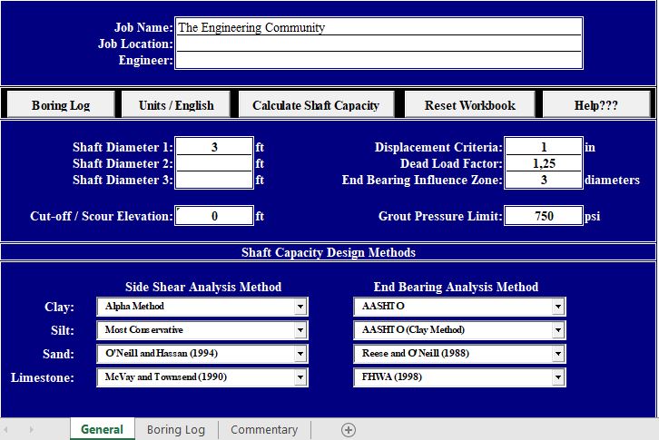
Shaft Capacity Calculation Spreadsheet
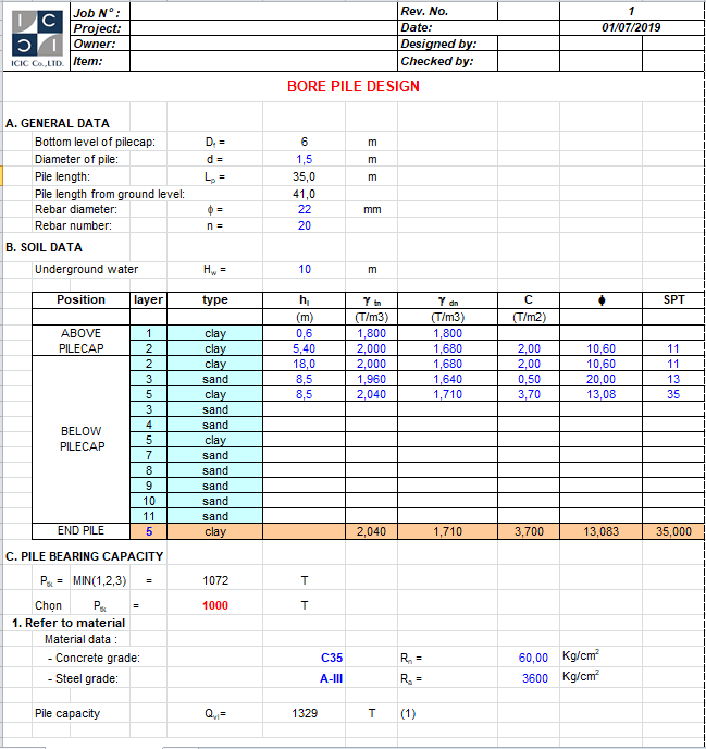
Bore Pile Design Bs 8004 Excel Sheet

Coupling Beam Design Excel Sheet Excel Beams Design

Sheet Pile Wall Design Spreadsheet And Maintenance Schedule Template Excel Schedule Template Spreadsheet Design Spreadsheet Template
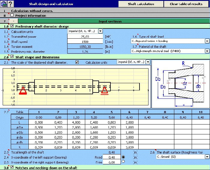
Mitcalc Shafts Shafts Design And Calculation Spreadsheet

Pile Design Spreadsheet Spreadsheet Design Spreadsheet Checklist Template

Design Calculation Using Excel Spreadsheet Download Scientific Diagram

Download Gambar Detail Standard Plumbing Dwg Autocad Autocad Referensi Gambar Shower
0 comments
Post a Comment